
Permanent Cabling
Record route length, fibre count, terminations and the spare-fibre policy.
Start with where the link begins and ends. Then bring together the cable, termination, patching and pathway parts that allow the connection to be installed, identified and maintained.
These product families are a starting point for a project brief. Request current drawings, compatibility details and the exact supplied configuration before final selection.
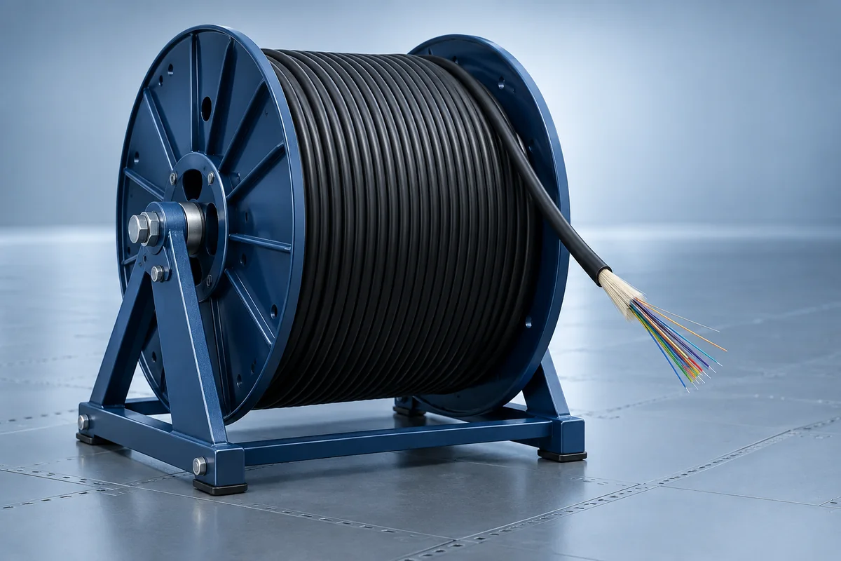
Connect equipment rooms across a campus with a construction suited to the actual duct, riser or external route.
Brief inputsRoute exposure, fibre category, core count, length and spare capacity.
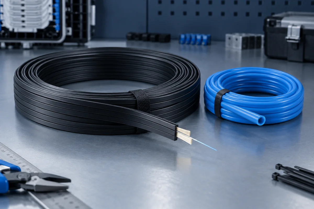
Plan the short connection from the distribution point to an individual unit or remote building endpoint.
Brief inputsPathway space, bending limits, entry method and endpoint termination.
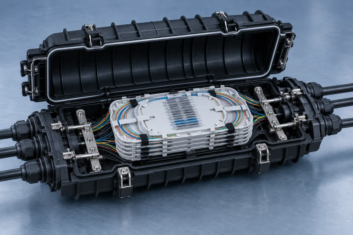
Protect cable joints and branches where an interbuilding route requires a serviceable splice point.
Brief inputsCable count, diameters, splice capacity, sealing and re-entry access.
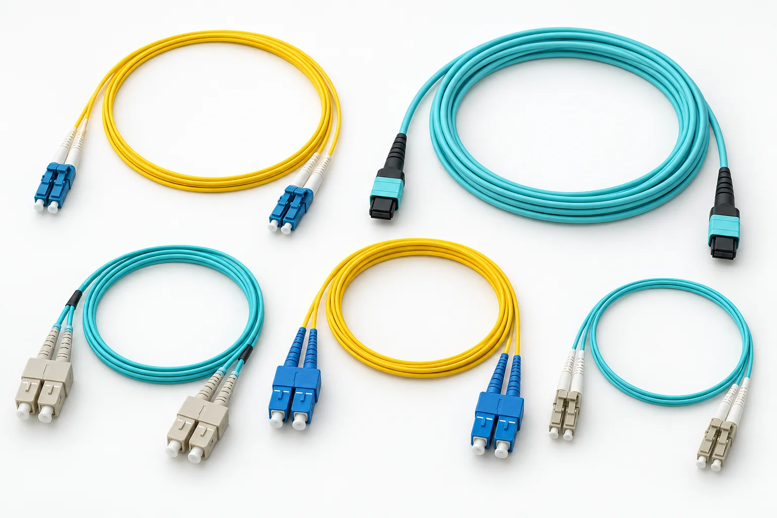
Link the permanent cabling to switches, transceivers and neighbouring patch panels without excess unmanaged slack.
Brief inputsConnector pair, polish, fibre type, length, jacket and loss allowance.
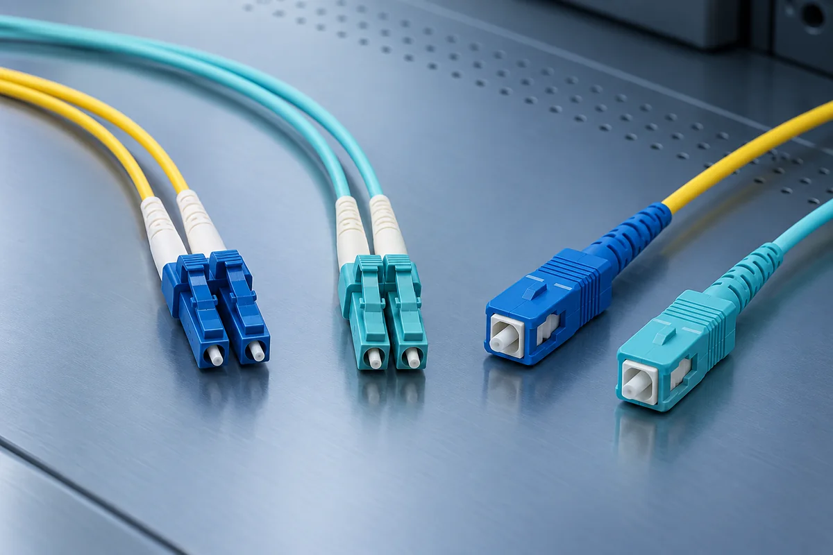
Align panel and equipment interfaces while keeping connector format and end-face polish clearly identified.
Brief inputsConnector format, simplex or duplex layout, polish and mounting.
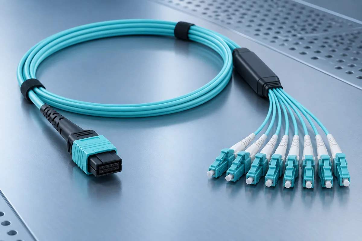
Organise high-fibre-count links and equipment breakouts with an end-to-end polarity plan.
Brief inputsFibre count, pinning, polarity, connector type and cassette interface.
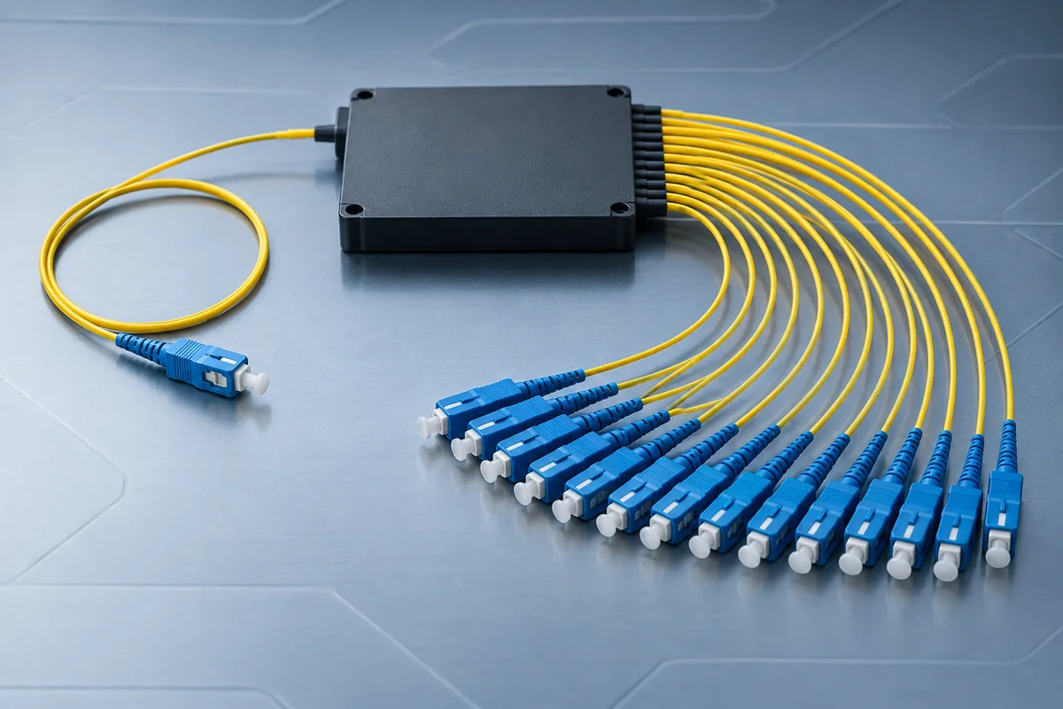
Distribute a PON connection to multiple endpoints where the system architecture and power budget support it.
Brief inputsSplit ratio, package, connectors, location and total optical loss.
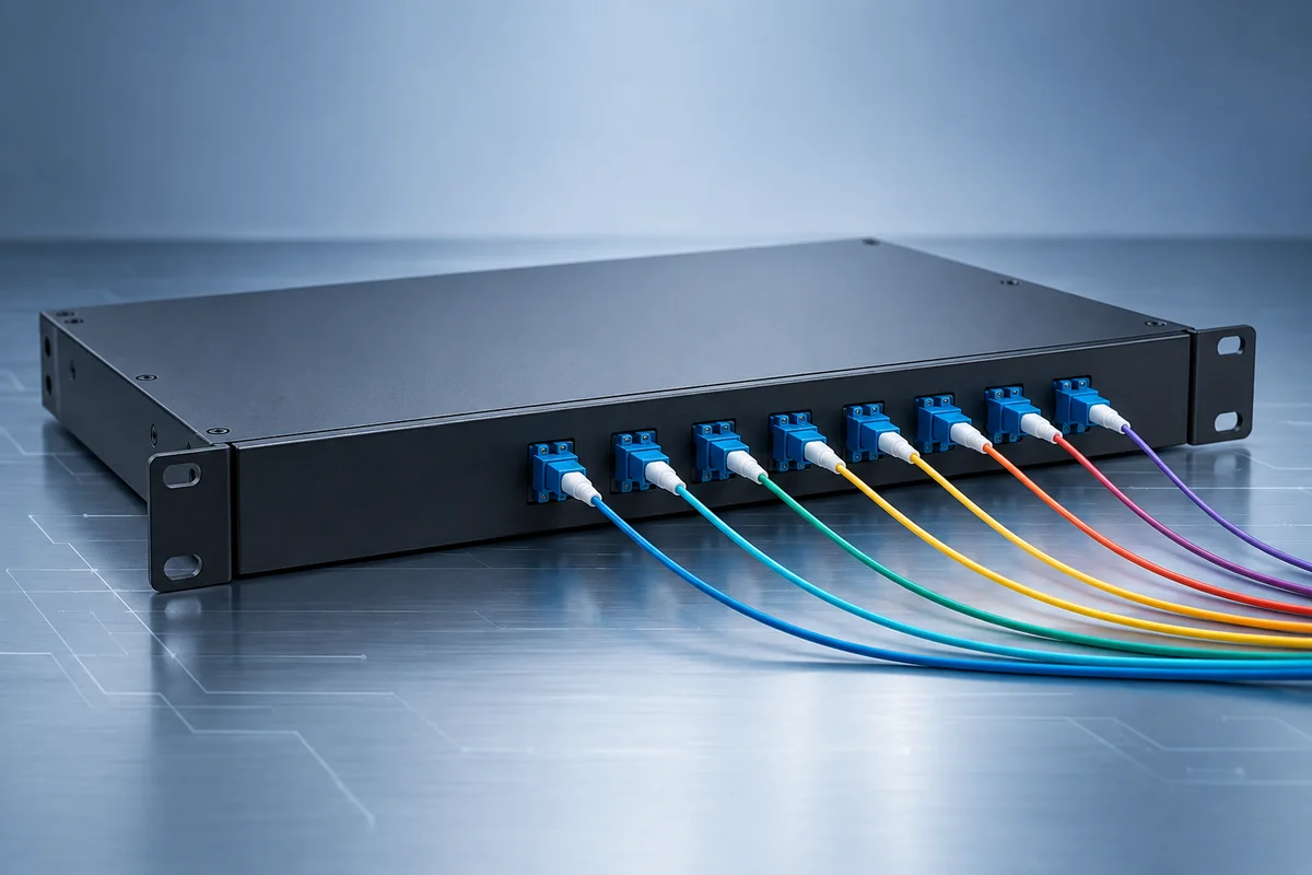
Assess wavelength-based expansion when existing fibre paths need to carry additional compatible services.
Brief inputsWavelength plan, channel count, end equipment and link loss.
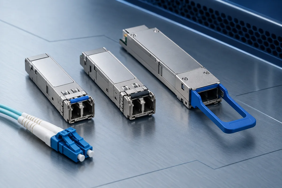
Match both link endpoints to the host equipment, fibre path and intended service rather than nominal speed alone.
Brief inputsHost support, form factor, data rate, wavelength and optical budget.
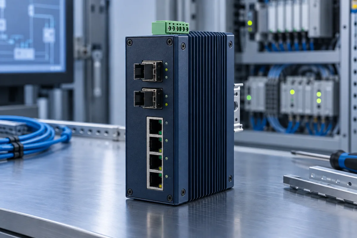
Bridge a supported copper Ethernet interface to fibre for a remote room, monitoring point or building link.
Brief inputsEthernet interface, fibre optics, power, enclosure and operating conditions.
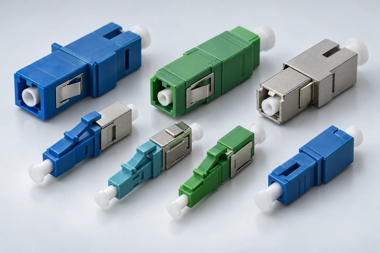
Control received optical power where a verified link calculation shows that attenuation is needed.
Brief inputsRequired attenuation, wavelength, connector, polish and receiver limits.
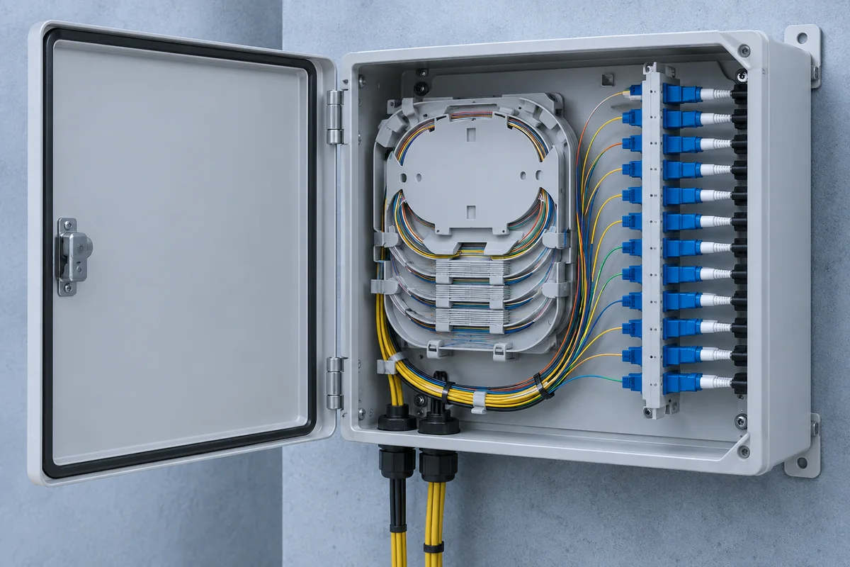
Provide a defined termination point close to a floor, tenant area or small local equipment cluster.
Brief inputsPort count, mounting, cable entry, splice provision and accessibility.
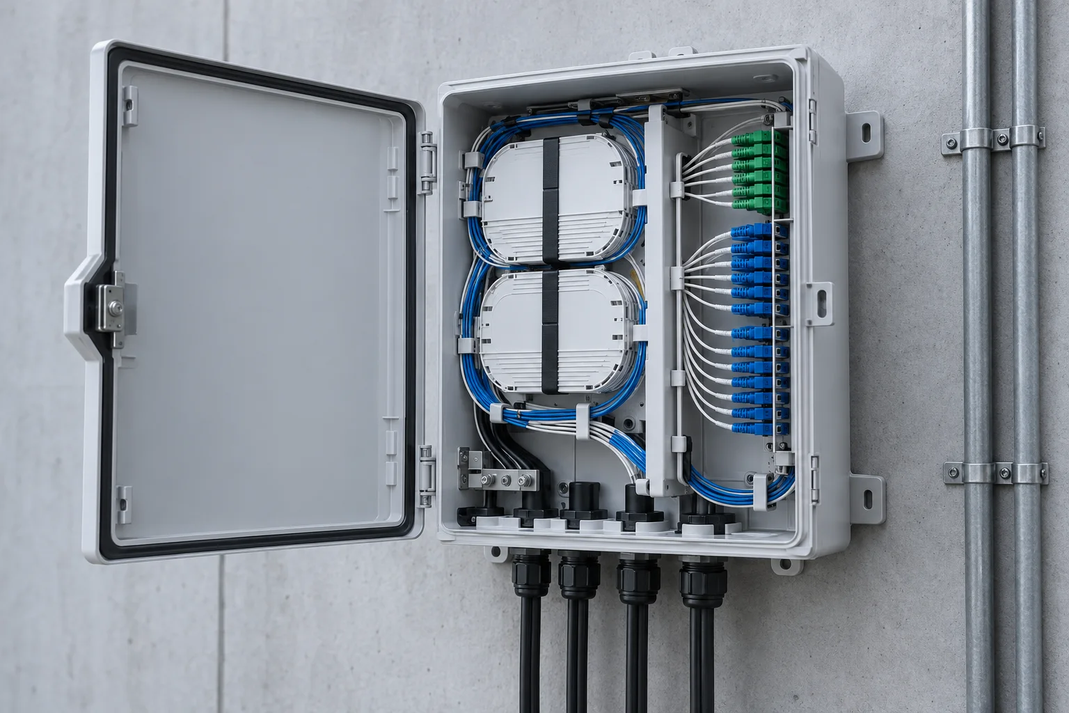
Coordinate feeder termination and onward fibre connections in a shared building distribution location.
Brief inputsFeeder count, outgoing connections, splice storage and maintenance access.
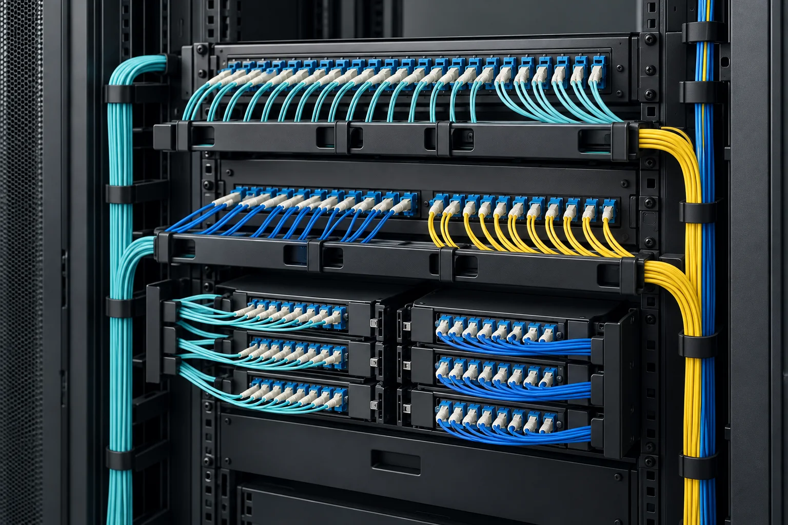
Make the permanent cable plant visible and serviceable at the rack, with clear separation from equipment jumpers.
Brief inputsRack units, ports, adapters, rear cable entry and splice arrangement.
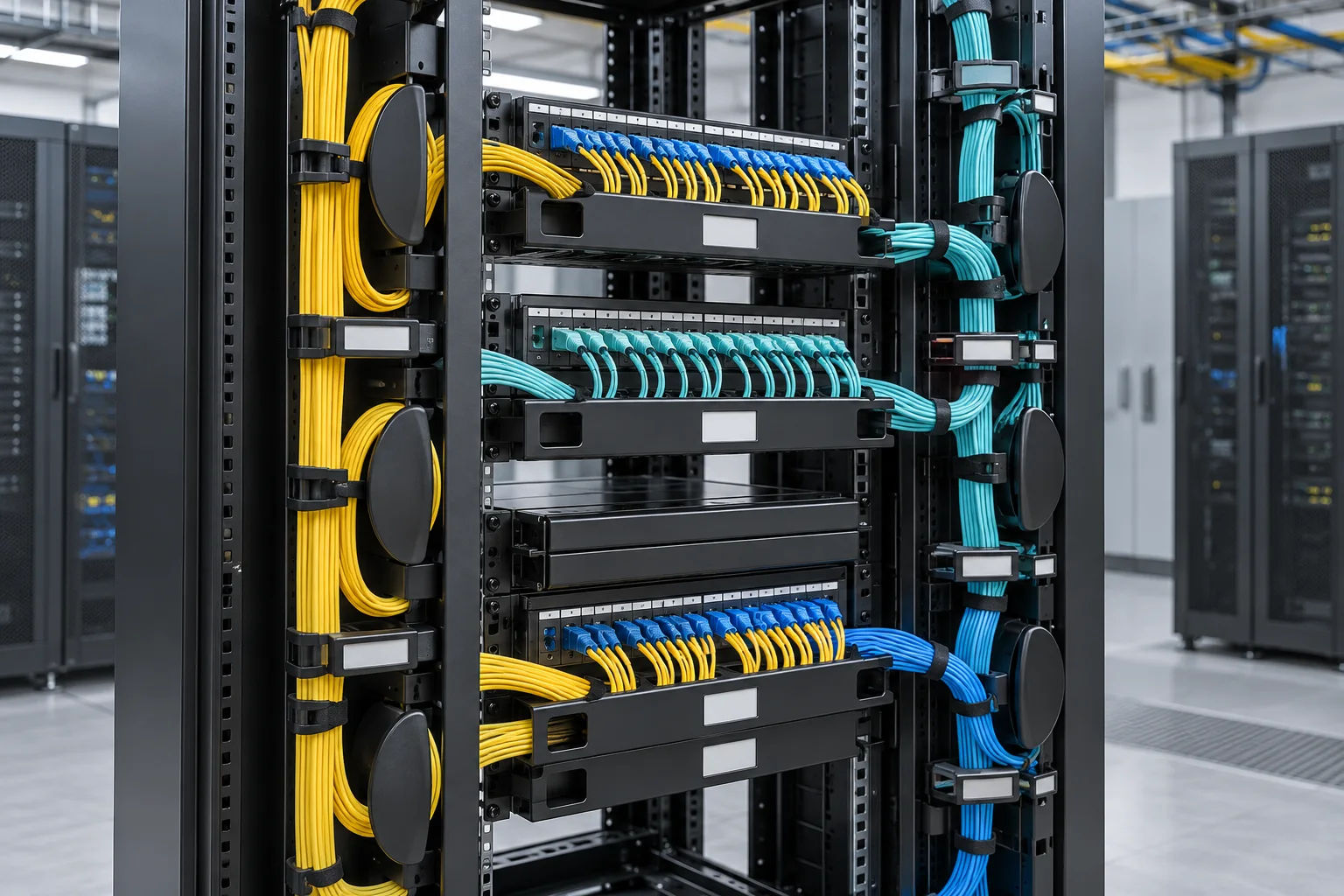
Route and retain jumpers so that labels, doors, equipment access and future changes remain practical.
Brief inputsCable volume, direction, bend control, slack storage and rack layout.

Carry fibre between equipment rows and distribution points with coordinated branches and drops.
Brief inputsRoute geometry, fibre volume, support points, outlets and expansion.
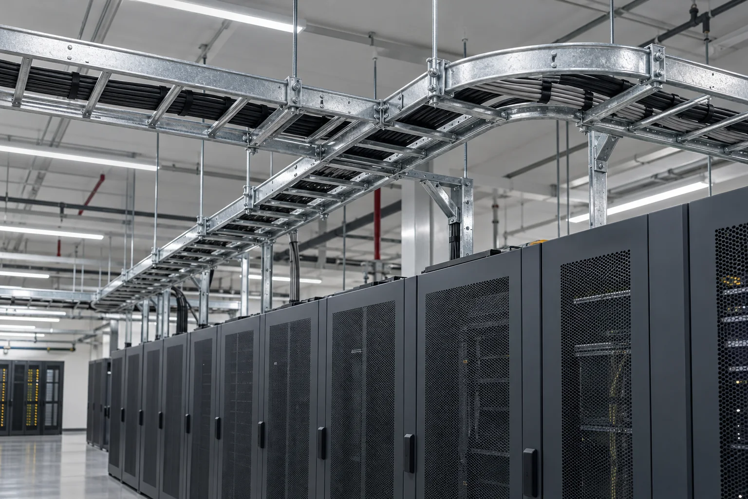
Plan supported pathways through service spaces while coordinating cable segregation and access.
Brief inputsCable load, route survey, support design, separation and available fill.
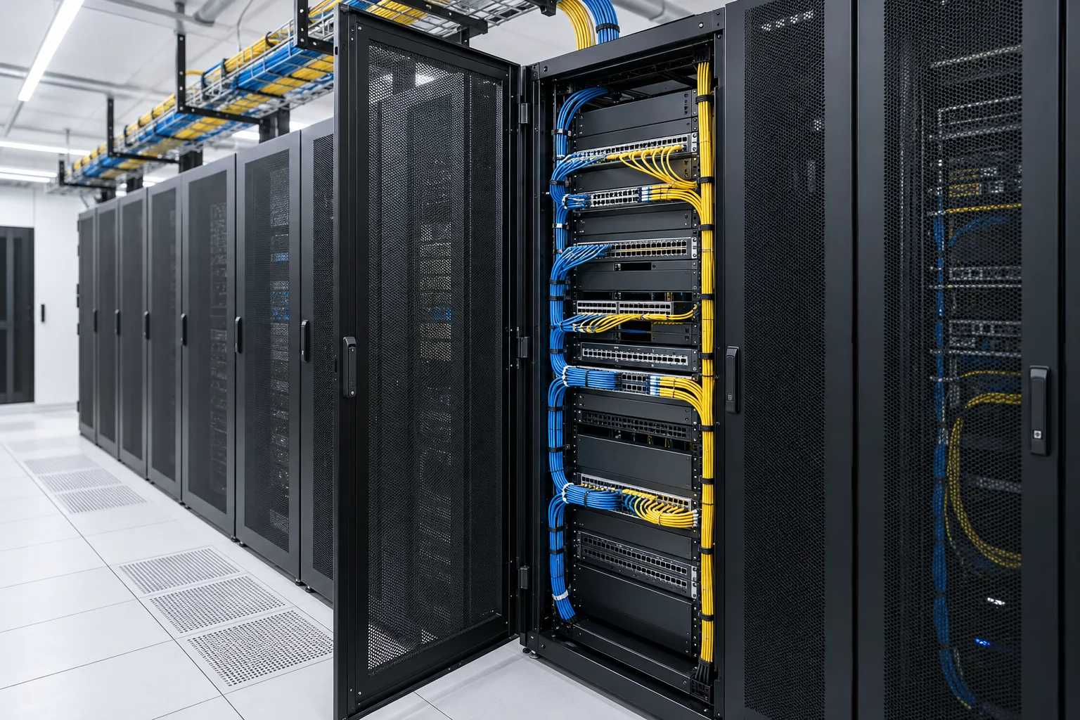
Bring panels, switches and cable management into a layout that supports installation and later changes.
Brief inputsEquipment depth, rack space, cable zones, access and ventilation.
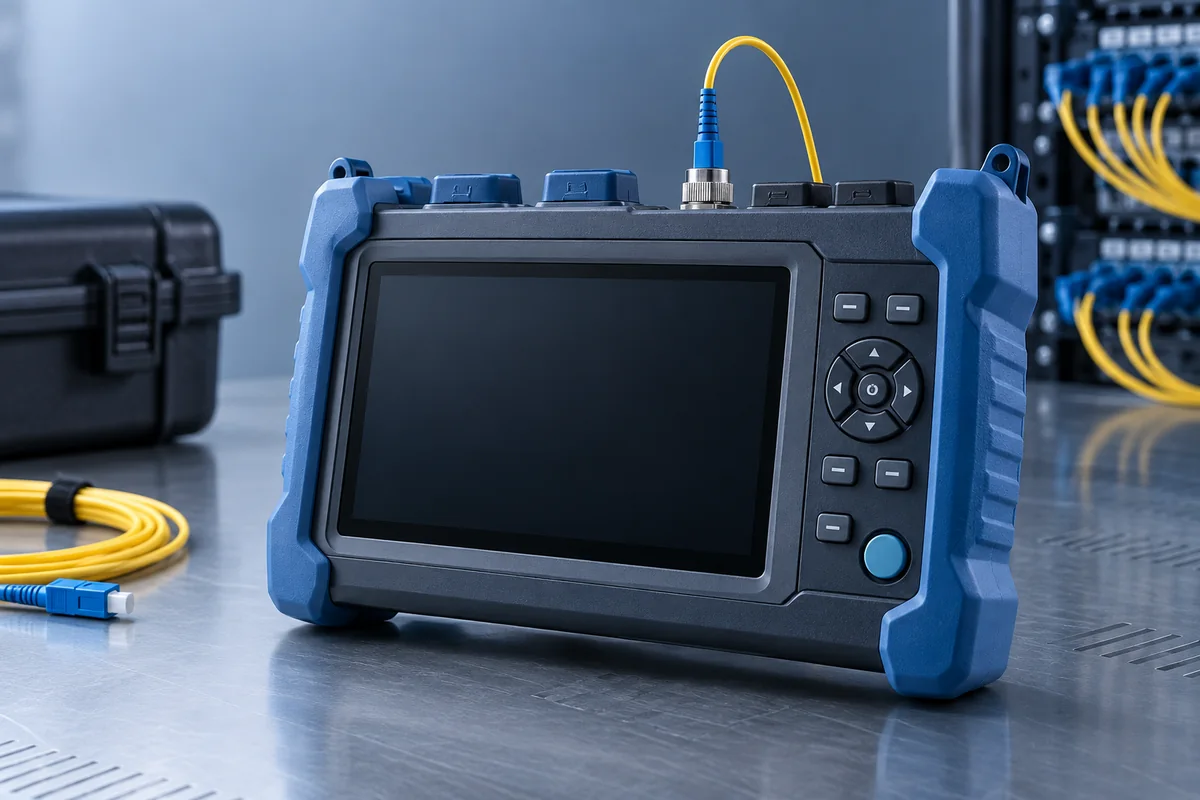
Locate and characterise events along a fibre path when the agreed test scope requires this evidence.
Brief inputsFibre type, wavelengths, range, launch leads and report format.
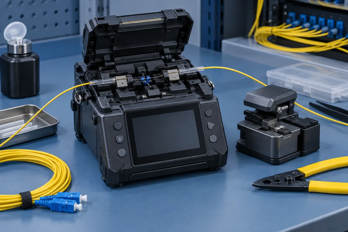
Prepare and join fibres with an equipment package appropriate to the fibre construction and field task.
Brief inputsFibre compatibility, preparation tools, splice protection and work conditions.
A panel, box or trunk assembly can mean different supplied configurations. Ask for the same scope when comparing product options and cost.
Record route length, fibre count, terminations and the spare-fibre policy.
List adapters, pigtails, patch leads, cassettes and polarity requirements.
Include brackets, trays, glands, bend guides, labels and pathway fittings.
Define identification, test results, as-built records and handover files.
Mark the known details and the decisions that are still open.